

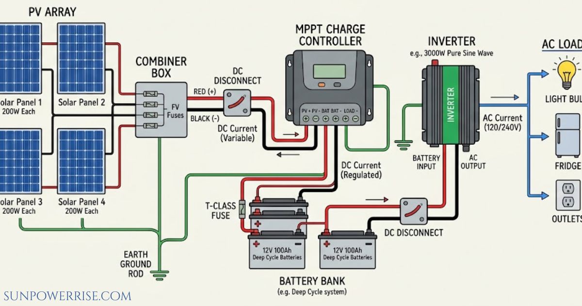
I sat down with a solar panel wiring diagram spread across my workbench, trying to figure out the quickest route from panel to battery. Solar panel wiring and a solar panel wiring process are not just about connecting wires; they decide how your whole setup behaves, and that starts with picking between series wiring and parallel wiring.
For an RV, a boat, or most off-grid solar installations, series wiring tends to win because it delivers higher voltage, lower current, and lets you get away with smaller wires, less power loss, and lower cost overall the roadmap simply gets shorter and cheaper.
Parallel wiring earns its place when panels facing different directions or partial shading come into play, or when you’re stuck with a basic PWM charge controller that can’t handle much else.
Still, choosing between series and parallel connections for your PV modules is a decision you can’t skip, and larger setups often blend both into a hybrid solar panel array. Some modules even ship with built-in microinverters, which changes how the whole array gets wired.
What Is a Solar Panel Wiring Diagram?
Think of it as the paperwork installers lean on before they ever pick up a tool a blueprint that lets you configure the connection on paper first so you don’t discover errors halfway through a rooftop install.
It traces where radiant sun energy actually travels once it leaves the panel, and honestly, that visual clarity saves hours during the installation process.
In plain terms, these are graphic representations of every connection between each PV module and the rest of the solar power system components, including the solar inverter, the charge controller, the solar battery, the Battery Management System, the storage inverter, the Smart Home Panel, the transfer switch, and for anyone tied to the utility grid the bidirectional electric meter or smart meter used in grid-tied solar panel systems.

Once you’ve seen a handful of these diagrams, spotting a mislabeled connection on a real rooftop becomes second nature and honestly, that’s the fastest way to actually learn how to wire solar panels correctly.
Practical Guide for Solar Panel Wiring
Before you commit to a layout, nail down your system voltage most home setups run 12V, 24V, or 48V systems, and the right pick depends on your energy needs and must stay consistent across battery, panels, and inverter.
Controller Selection & Battery Setup
Next comes charge controller type: MPPT suits a series connection best, while PWM only makes sense once panel and battery voltage match. Your battery bank setup matters too: decide on single wiring, series battery wiring, or parallel battery wiring, keeping the cabling manageable.
Cable Sizing & Overcurrent Protection
Get proper cable sizing right so you avoid no voltage drop issues, always reaching for the correct wire gauge to handle your expected current flow. Every solar panel wire you run should match that rating, and never skip fuses and breakers, since they guard against overloading.
Controller Voltage & Capacity Limits
A quick charge controller check tells you how much room you have: a Basic PWM unit tops out near ~30V and handles roughly 1-2 panels, an Entry MPPT stretches to 75-100V for 3-5 panels, a Mid-range MPPT covers 100-150V across 6-8 panels, and a High-end MPPT reaches 150-250V, enough for 10+ panels.
String Sizing & Safety Margins
Build in a safety margin by keeping your string 10% below controller limits, since cold weather pushes panel voltage upward. A simple string size calculation a formula dividing controller max voltage by panel Voc and a safety factor does the heavy lifting: a 100V controller paired with 22V Voc panels allows about 4.1 panels maximum per string.
Once your string size is locked in, move to wire sizing. Match string current to distance and gauge: 5-6A over 30 ft calls for 14 AWG, 8-10A over the same 30 ft needs 12 AWG, and anything in the 15-20A range wants 10 AWG as the minimum gauge. Skimp here and you’ll pay for it in heat and voltage drop later.
Preparation Before Designing Solar Panel Wiring Diagram
Good planning for any electrical wiring for solar panels is what separates a safe and effective design from a rooftop headache, and it starts with picking your drawing medium.
Manual Drawing
Manual drawing works fine for a small solar system, but once you’re managing large systems with a huge number of connections across multiple devices, pencil and paper stop scaling it’s forgiving for beginners, though hard to fix once you try to modify manual drawings.
Digital Drawing
Digital drawing solves that: it produces precise, scalable diagrams suited to professional diagrams, using digital tools such as Microsoft Visio, AutoCAD, or Draw.io, letting you scale up diagram work for bigger projects with real professional tools I lean on a solar connectivity digital diagram myself for anything beyond a single string.
From there, nail down the basic components of solar system: the solar panels themselves, the inverter that turns Direct Current into Alternating Current since most devices run on AC energy, the charge controller that’s busy regulating voltage and current.
The batteries that keep off-grid systems running by storing energy for cloudy or nighttime use, and finally the disconnects and fuses that let you isolate system components safely in case of a malfunction.
Avoid Common Wiring Mistakes
Even seasoned installers slip up sometimes, so it’s worth naming the common wiring mistakes outright. Top of the list is incorrect series/parallel configuration mixing series and parallel connections hands you wrong voltage and a useless system, so double-check both your charge controllers and inverters match.
Ignoring polarity is just as costly: swap a positive terminal with a negative terminal, and you can damage the charge controller, damage the inverter, or damage battery components in one careless moment, so always double-check connections against the diagram before you flip the switch.
An undersized wire gauge invites voltage drop and overheating, so stick to standard wiring sizes every time.
Unlabeled diagrams or confusing diagrams cause just as much trouble proper labelling of voltage, current ratings, wire types, and directions prevents you from confuse installers or introducing new errors.
Skipping the charge controller and choosing to connect panels directly to batteries is a shortcut toward a poor unsafe design. And don’t fall into overcomplicating the layout with unnecessary crossovers a diagram hard to follow helps nobody on installation day.
FAQs
How should solar panels be wired?
Wire panels in series for higher voltage and lower current, or in parallel for steady voltage with more current the right solar panel wiring diagram depends on your charge controller and energy needs.
What are common solar panel wiring mistakes?
The biggest wiring mistakes are ignoring polarity, using undersized wire gauge, and mixing series and parallel connections small slip-ups that can quietly damage your whole system.
How can I tell which wire is positive and negative on solar panels?
Check the positive terminal and negative terminal markings on the panel’s cables or connectors most use color-coded, standardized connectors like the Universal Solar Connector so you never have to guess.
Can I wire a solar panel straight to a battery?
Technically yes, but it’s risky skipping the charge controller invites overloading and can damage battery cells fast, so it’s best avoided.
How are solar panels wired to mains?
For grid-tied solar panel systems, panels connect through a solar inverter that converts DC to AC, then ties into your home’s mains via a bidirectional smart meter.